
HVAC Ductwork Design Guide (Layout, Duct Size & CFM) – Complete Expert Guide
Designing HVAC ductwork is one of the most critical aspects of any air conditioning system. Whether you’re working on a residential project, commercial building, or industrial HVAC system, proper duct design ensures efficient airflow, energy savings, and occupant comfort.
This guide will walk you through everything—from CFM calculation to duct layout, sizing, static pressure, and expert design tips—based on real-world practices and your reference content .
1. Introduction to HVAC Ductwork Design
HVAC ductwork is the distribution system that delivers conditioned air from your HVAC unit to different spaces.
A well-designed duct system ensures:
- Proper airflow distribution
- Energy efficiency
- Low noise operation
- Balanced cooling/heating
As explained in your reference, duct design is a step-by-step engineering process, not guesswork .
2. Fundamentals of Airflow (CFM, BTU, Ton)
Before designing ducts, you must understand these core concepts:
Key Terms:
- CFM (Cubic Feet per Minute) → Airflow volume
- BTU (British Thermal Unit) → Cooling capacity
- Ton of Refrigeration → 12,000 BTU
Rule of Thumb:
- 1 Ton = 400 CFM
This means:
- 2 Ton AC → 800 CFM
- 3 Ton AC → 1200 CFM
This rule is widely used for quick duct sizing.
In this guide, I will use a layout drawing created in AutoCAD as an example to show you step-by-step how to design HVAC ductwork for homes.
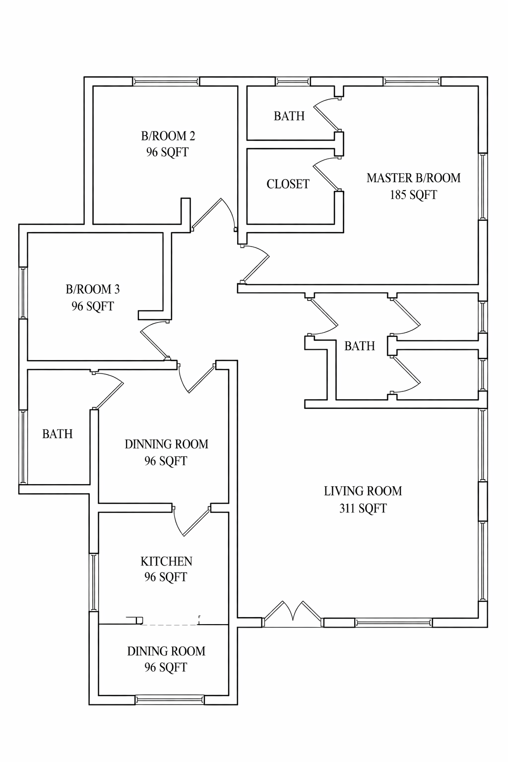
3. Step 1: Calculate CFM for Each Room
The first step in duct design is determining airflow requirements per room.
Formula:
CFM=BTU / 30
This comes from:
- 12000 BTU ÷ 400 CFM = 30
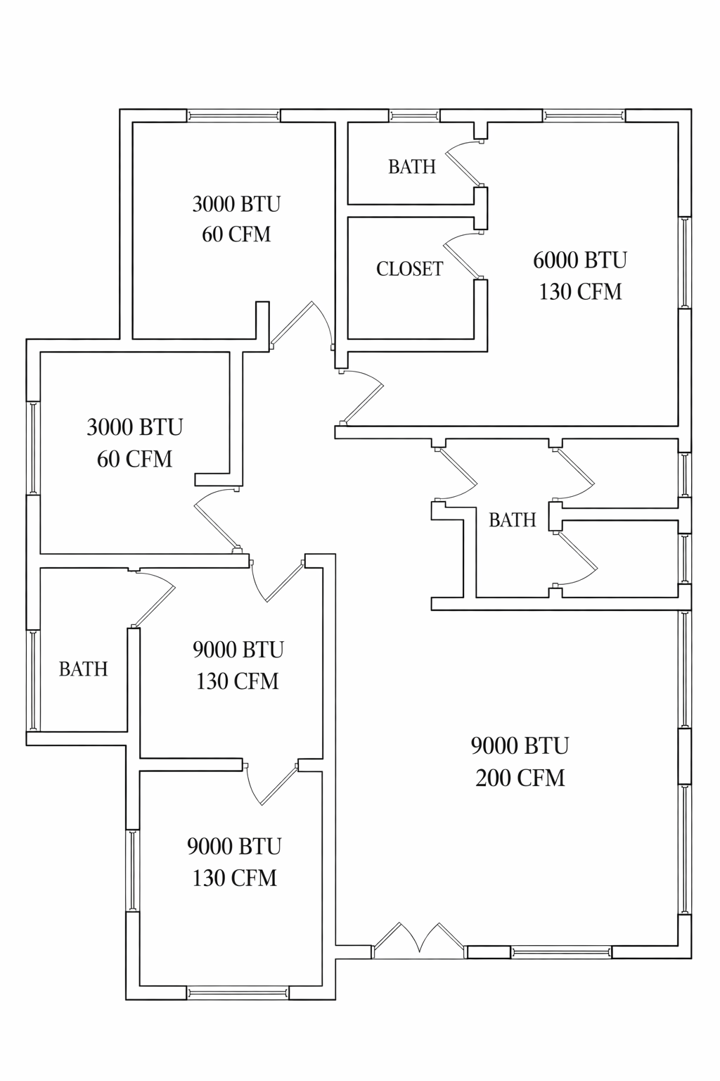
Example Calculation
| Room | Area | BTU | CFM |
|---|---|---|---|
| Living Room | 300 sq.ft | 9000 | 300 |
| Kitchen | 200 sq.ft | 9000 | 300 |
| Bedroom 1 | 200 sq.ft | 6000 | 200 |
| Bedroom 2 | 100 sq.ft | 3000 | 100 |
| Bedroom 3 | 100 sq.ft | 3000 | 100 |
Total = 1000 CFM
This matches a 2.5 Ton system
This exact method is highlighted in your reference guide .
4. Step 2: Supply & Return Layout Planning
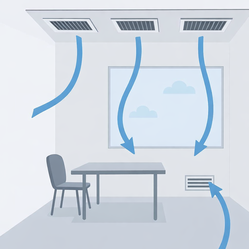
Supply Diffuser Placement
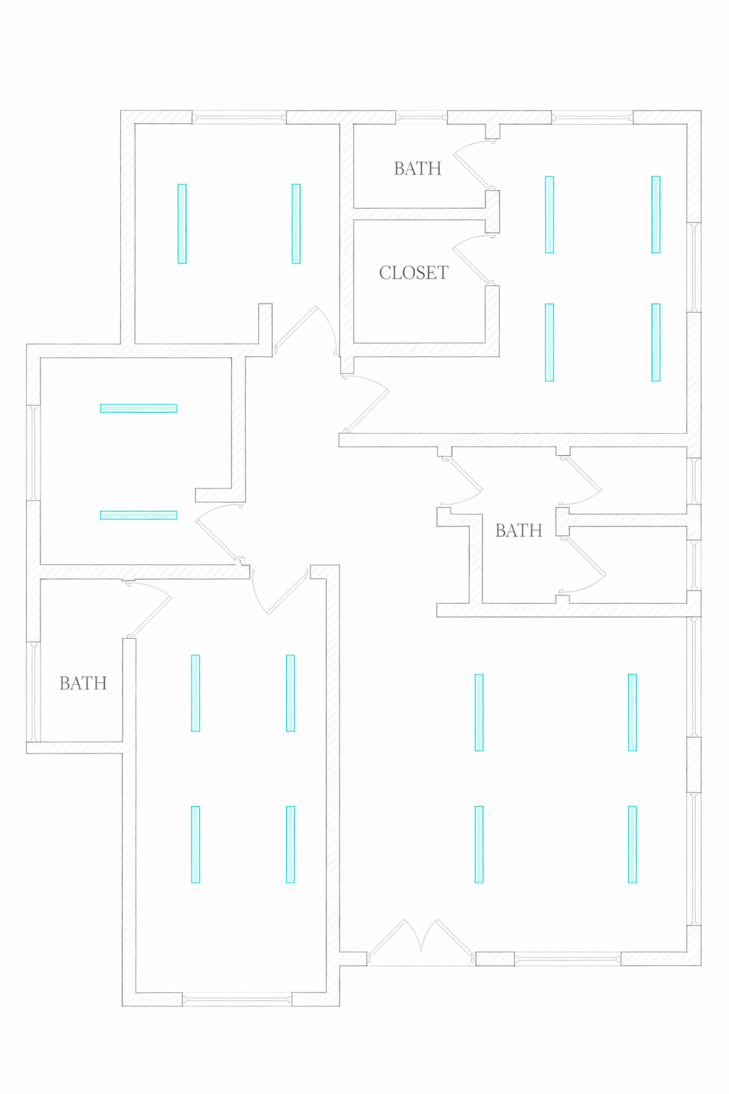
Best Practices:
- Place near ceiling for better air mixing
- Avoid placing near hot windows
- Use multiple diffusers for large rooms
- Maintain symmetry
More diffusers = lower noise + better distribution
Return Grille Placement
Rules:
- Place opposite supply diffusers
- Avoid short air circulation
- One return per room recommended
Ensures full room air circulation (important insight from reference )
5. Step 3: Duct Layout Design (Main + Branch)
Types of Duct Layout
- Trunk & Branch System
- Radial System
- Extended Plenum System
Design Process
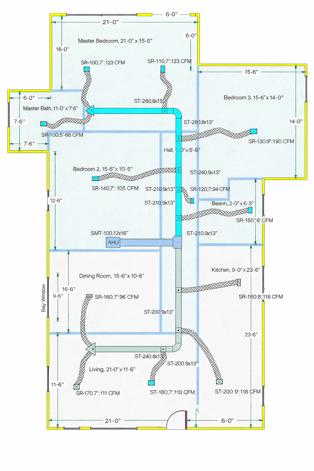
Steps:
- Start from HVAC unit
- Draw main trunk duct
- Branch ducts to each room
- Connect diffusers via flexible ducts
Important Design Elements:
- Main duct = total airflow
- Branch duct = reduced airflow
- Use duct reducers after branches
- Maintain proper duct height
As noted in reference, duct height must allow flexible duct connection .
6. Step 4: Duct Sizing Methods
Common Methods
- Equal Friction Method
- Static Regain Method
- Velocity Reduction Method
Simplified Duct Sizing (Practical)
| CFM | Round Duct Size |
|---|---|
| 100 | 6 inch |
| 200 | 8 inch |
| 300 | 10 inch |
| 400 | 12 inch |
Key Rules:
- Velocity:
- Main duct: 700–900 FPM
- Branch duct: 500–700 FPM
- Avoid:
- Too small → noise
- Too large → cost
7. Step 5: Return Air Duct Design
Return Duct System
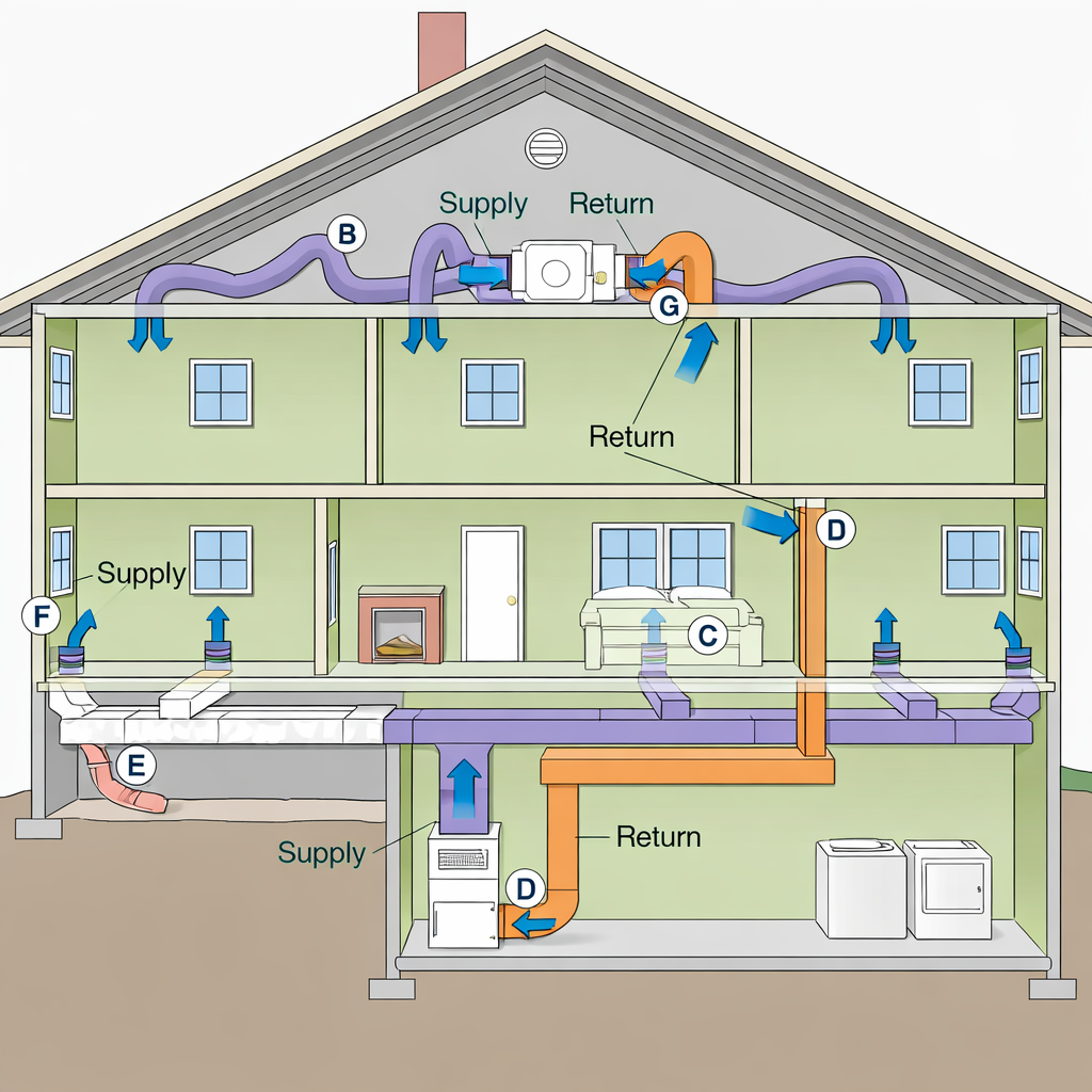
Options:
1. Ducted Return
- Required for multi-room systems
- Best airflow control
2. Free Return
- Uses ceiling plenum
- Suitable for small areas
Key Component:
- Return Plenum Box
Essential for connecting return ducts to AHU
8. Step 6: Fresh Air Ventilation Design
Fresh Air Intake System
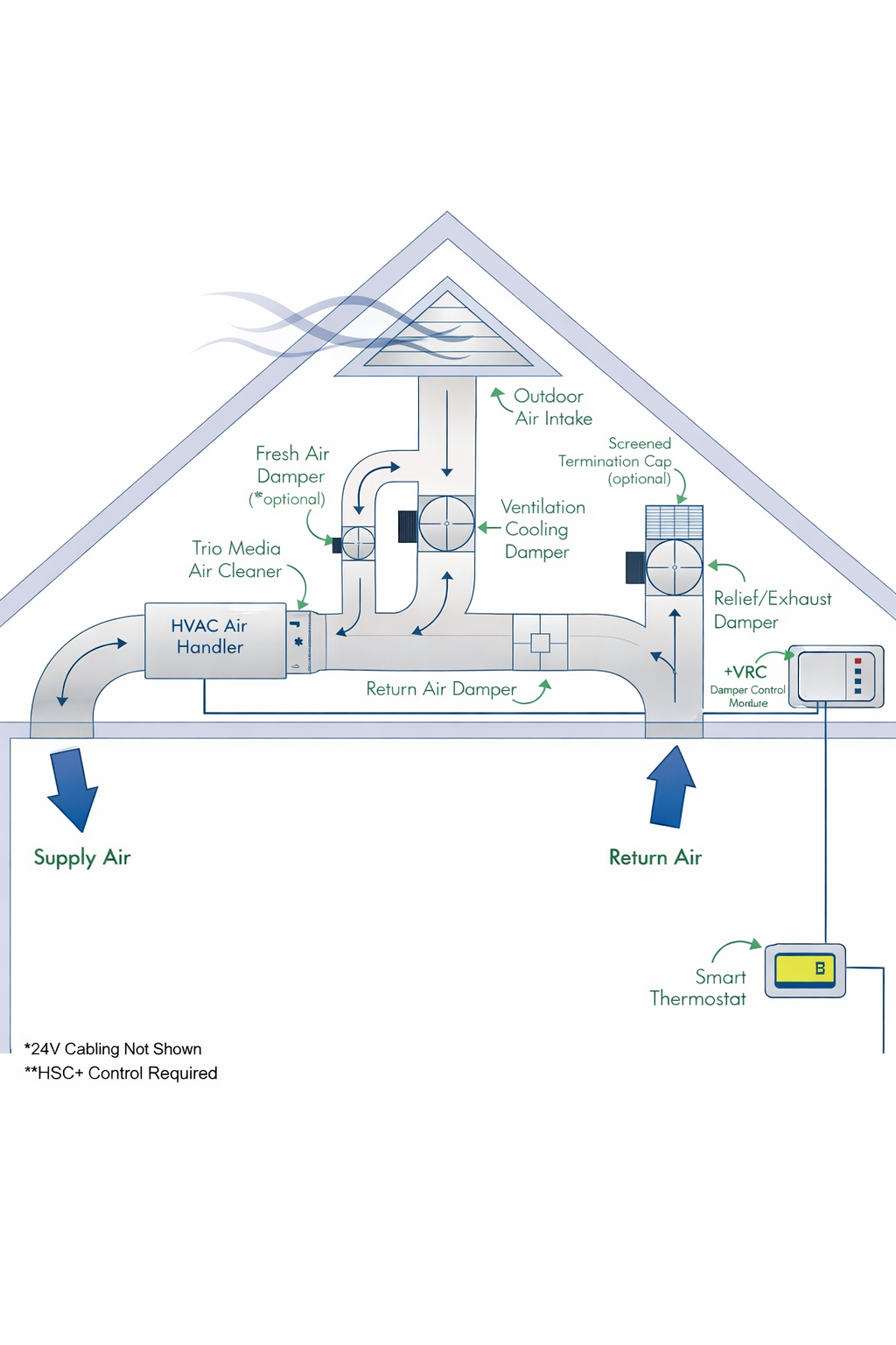
Design Guidelines:
- Fresh air = 10% of total airflow
- Connect to return plenum
- Install Volume Control Damper (VCD)
Improves indoor air quality (IAQ)
9. Step 7: Static Pressure & Friction Loss
This is the most critical step for system performance.
Friction Loss Components:
- Straight duct
- Elbows
- Diffusers
Example Calculation:
- Straight duct = 38 ft
- Loss = 0.038 in.wg
- Elbows = 2 × 16 ft = 32 ft
- Loss = 0.032 in.wg
- Diffuser = 0.1 in.wg
Total:
Total=0.17 in.wg
Matches safe range (0.2–0.4 in.wg)
10. HVAC Design Best Practices
- Use guide vanes in branch ducts
- Install volume control dampers
- Maintain minimum duct height
- Avoid duct intersections
- Use flexible ducts properly
11. Common Mistakes in Duct Design
- Wrong CFM calculation
- Poor diffuser placement
- Undersized ducts
- No balancing dampers
- Ignoring static pressure
12. Tools & Software for Duct Design
- AutoCAD (Layout)
- Revit MEP
- Ductulator
- HVAC design calculators
13. Expert Recommendations (Pro Tips)
From HVAC Industry Experience:
- Always oversize return air slightly
- Keep duct routing simple
- Balance airflow after installation
- Use insulation to prevent losses
14. Conclusion
HVAC ductwork design is a technical + practical skill that combines:
- Engineering calculations
- Layout planning
- Field experience
By following this complete guide:
- You can design efficient systems
- Reduce energy costs
- Improve comfort
As shown in your reference, step-by-step design is the key to success
Frequently Asked Questions (HVAC Duct Design)
1. What is HVAC ductwork design?
HVAC ductwork design is the process of planning and sizing air ducts to distribute conditioned air efficiently throughout a building. It includes airflow calculation, duct sizing, layout design, and static pressure analysis.
2. How do you calculate CFM for a room?
CFM is calculated using the formula:
CFM = BTU ÷ 30
For example, a room requiring 6000 BTU needs:
👉 6000 ÷ 30 = 200 CFM
3. What is the standard CFM per ton in HVAC?
The standard rule is:
👉 1 Ton = 400 CFM
This means a 2-ton AC requires 800 CFM airflow.
4. How do you determine duct size?
Duct size depends on airflow (CFM) and velocity (FPM).
Formula used:
👉 Duct Area = CFM ÷ Velocity
Then convert area into duct diameter or rectangular size.
5. What is the ideal duct velocity?
- Main duct: 700–900 FPM
- Branch duct: 500–700 FPM
Lower velocity reduces noise and improves comfort.
6. Why is static pressure important in duct design?
Static pressure determines how well air flows through ducts. High pressure causes poor airflow, noise, and energy loss.
7. Should every room have a return air duct?
Yes, ideally every room should have a return air path to ensure proper air circulation and balanced cooling.
8. What is fresh air intake in HVAC?
Fresh air intake introduces outdoor air into the system, usually about 10% of total airflow, improving indoor air quality.
9. What are common mistakes in duct design?
- Incorrect CFM calculation
- Undersized ducts
- Poor diffuser placement
- Ignoring static pressure
10. What is the best duct design method?
The most commonly used method is the Equal Friction Method, which balances airflow and minimizes pressure loss.
Need Perfect HVAC Duct Design?
Stop guessing duct sizes and airflow. Get professional HVAC design support today.
- Accurate CFM & duct sizing
- Energy-efficient system design
- Reduced installation cost
📱 Call / WhatsApp: +91-9825636606
🌐 Website: www.vipulhvacsolution.in
📧 Email: info@vipulhvacsolution.in