How to Read HVAC Duct Drawings?
How to Read HVAC Duct Drawings?
Introduction
HVAC duct drawings are essential documents that show the layout, design, and airflow distribution of air conditioning and ventilation systems. For HVAC engineers, site supervisors, and technicians, the ability to read duct drawings correctly is a critical skill.
Many beginners struggle with:
- Symbols and abbreviations
- Duct sizes and airflow values
- Equipment tags
- System layout understanding
In this guide, you will learn step-by-step how to read HVAC duct drawings easily and professionally, based on real industry practices.
What is an HVAC Duct Drawing?
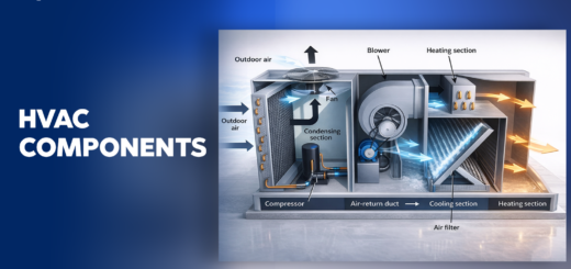
An HVAC duct drawing is a technical representation of air distribution systems, including:
- Duct routing
- Equipment (AHU, FCU, Fans)
- Diffusers and grilles
- Dampers and fittings
- Airflow direction and quantity
These drawings are mainly used for:
- Installation
- Coordination
- Fabrication
- Testing & commissioning
Basic Approach to Read HVAC Duct Drawings
According to industry best practices , follow this sequence:
Step 1: Identify Equipment Location
Step 2: Follow Duct Routing
Step 3: Check Duct Sizes
Step 4: Identify Grilles & Diffusers
Step 5: Understand Airflow Direction
Part 1: Air Conditioning System Drawings
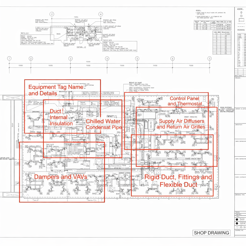
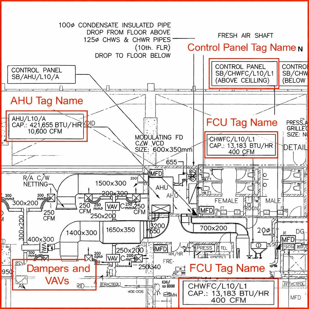
1. Equipment Tag Name & Details
Every HVAC equipment is labeled with a tag name and specifications.
Typical Information Includes:
- Tag Name
- Brand
- Model
- Cooling Capacity
- Airflow
- Static Pressure
- Weight
Example:
Common HVAC Equipment Acronyms
| Acronym | Meaning |
|---|---|
| AHU | Air Handling Unit |
| FCU | Fan Coil Unit |
| CHW | Chilled Water |
| CW | Condenser Water |
| VRF / VRV | Variable Refrigerant Flow |
These acronyms are heavily used in drawings to save space.
Cooling Capacity Units
| Unit | Conversion |
|---|---|
| BTU/hr | Base unit |
| TR (Ton) | 1 TR = 12,000 BTU/hr |
| kW | 1 kW = 3412 BTU/hr |
| HP | ~9000 BTU/hr |
2. Ducts, Fittings & Flexible Ducts
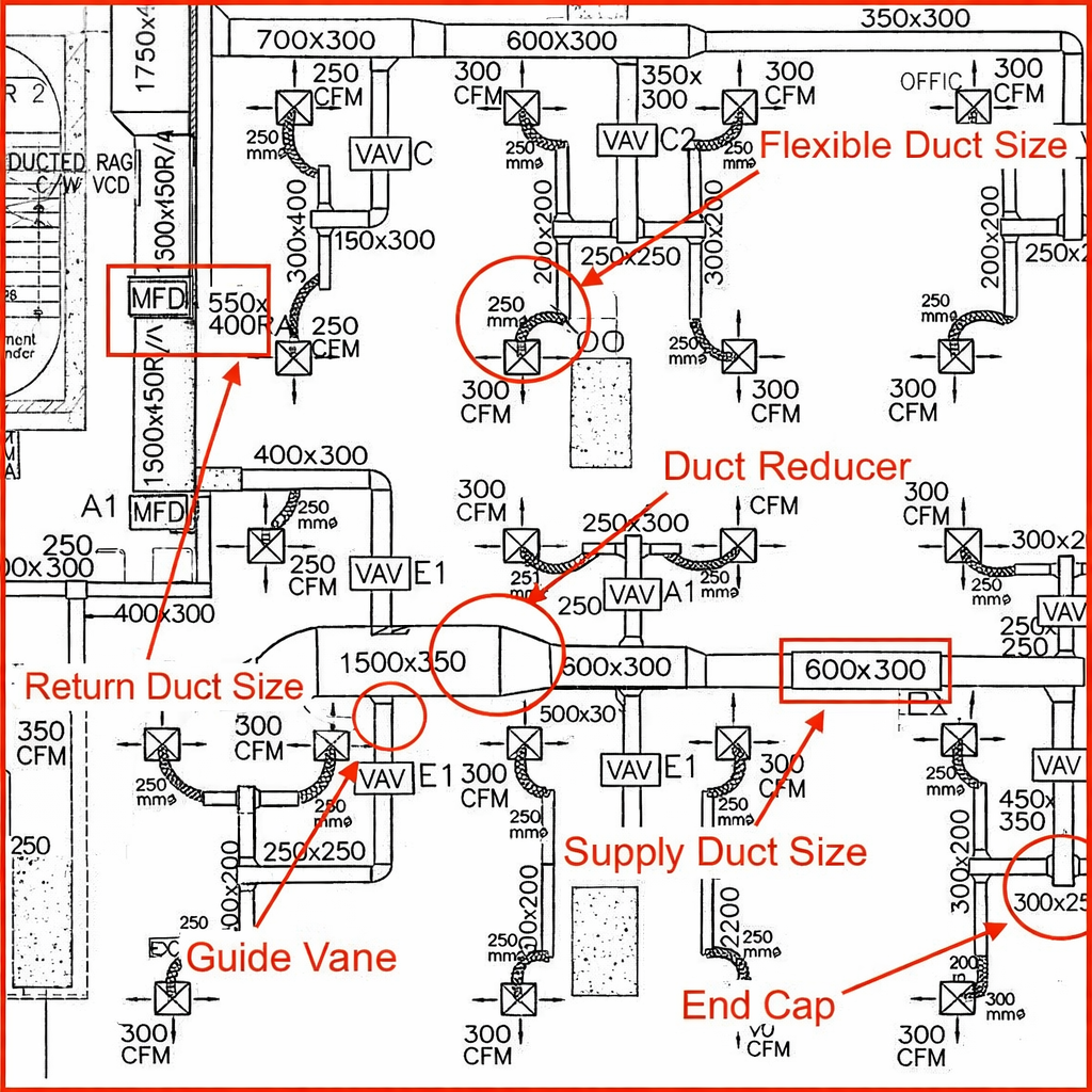
Ducts are shown in different forms:
Types:
- Rectangular duct
- Circular duct
- Flexible duct
Important Notes:
- Duct sizes exclude insulation thickness
- Flexible ducts connect diffusers
Common Duct Terms
| Acronym | Meaning |
|---|---|
| SA | Supply Air |
| RA | Return Air |
| FAD | Fresh Air Duct |
3. Supply Air Diffusers & Return Grilles
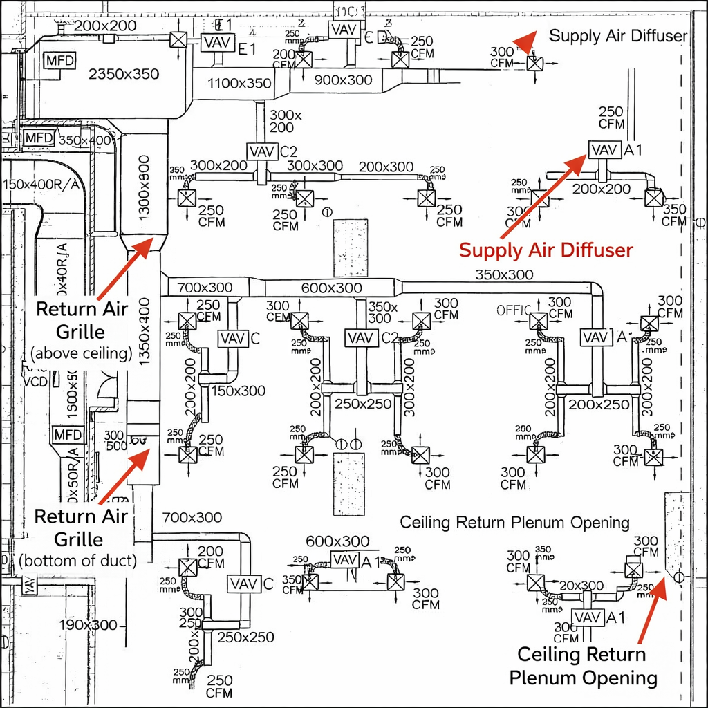
Understanding diffusers is key:
Types:
- Supply Air Diffuser (SAD)
- Return Air Grille (RAG)
Key Rule:
- With flexible duct → Supply diffuser
- Without flexible duct → Return grille
Important Concept: Return Air Plenum
- Ceiling space used as return path
- Reduces duct cost
- Common in commercial buildings
4. Dampers & VAV Systems
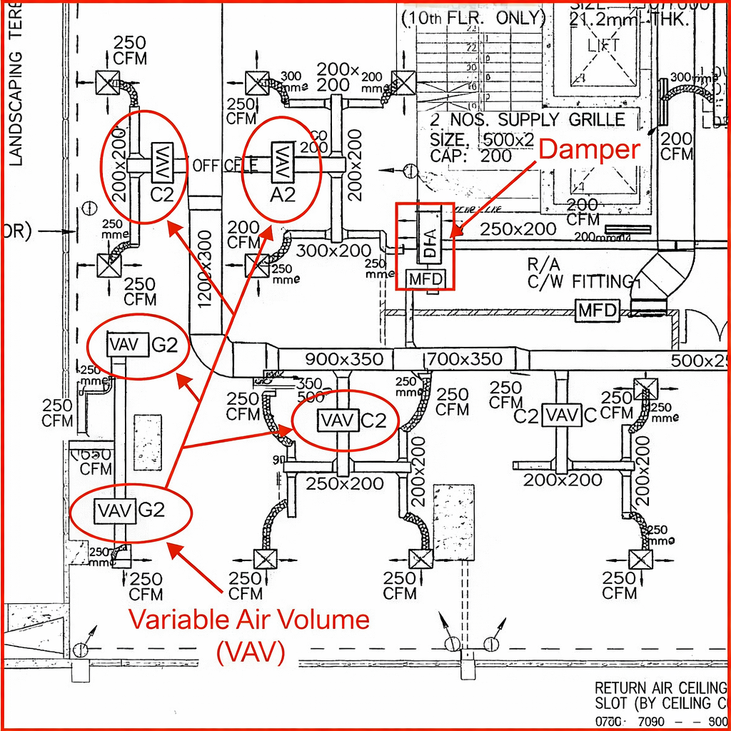
Dampers:
- VCD (Volume Control Damper)
- FD (Fire Damper)
VAV (Variable Air Volume)
- Controls airflow to zones
- Requires straight duct clearance (~600mm)
5. Duct Internal Insulation
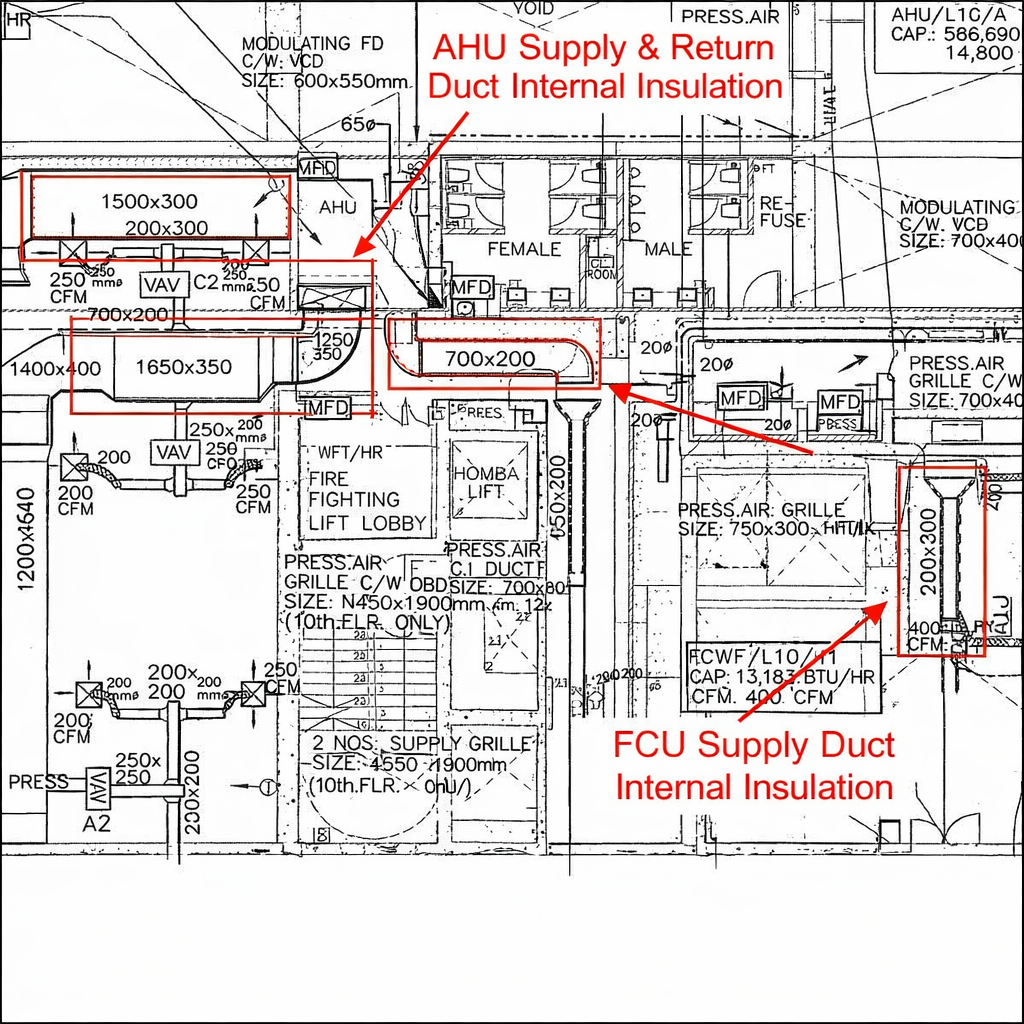
Shown as dotted lines inside duct
Purpose:
- Reduce noise
- Improve acoustic performance
6. Pipes in HVAC Drawings
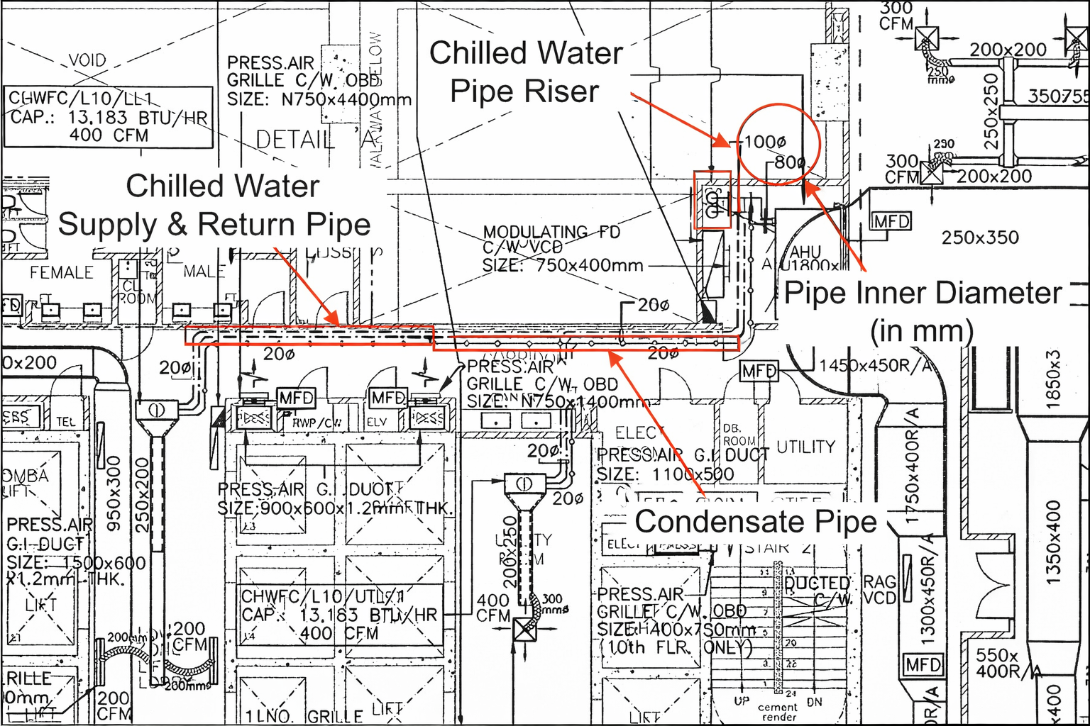
Types:
- Chilled water pipes
- Condensate pipes
Usually drawn as:
- Dotted lines
- Circle lines (for condensate)
7. Control Panel & Thermostat
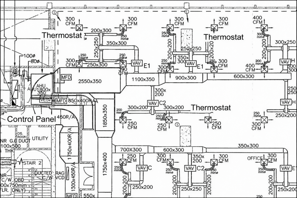
Symbols:
- Control panel → Rectangle with diagonal
- Thermostat → “T” symbol
Each VAV may have its own thermostat
8. Ceiling Manholes (Very Important)
- Used for maintenance access
- Often missed in drawings
- Can cause costly issues later
Part 2: Mechanical Ventilation System
1. Equipment Tag & Fan Details
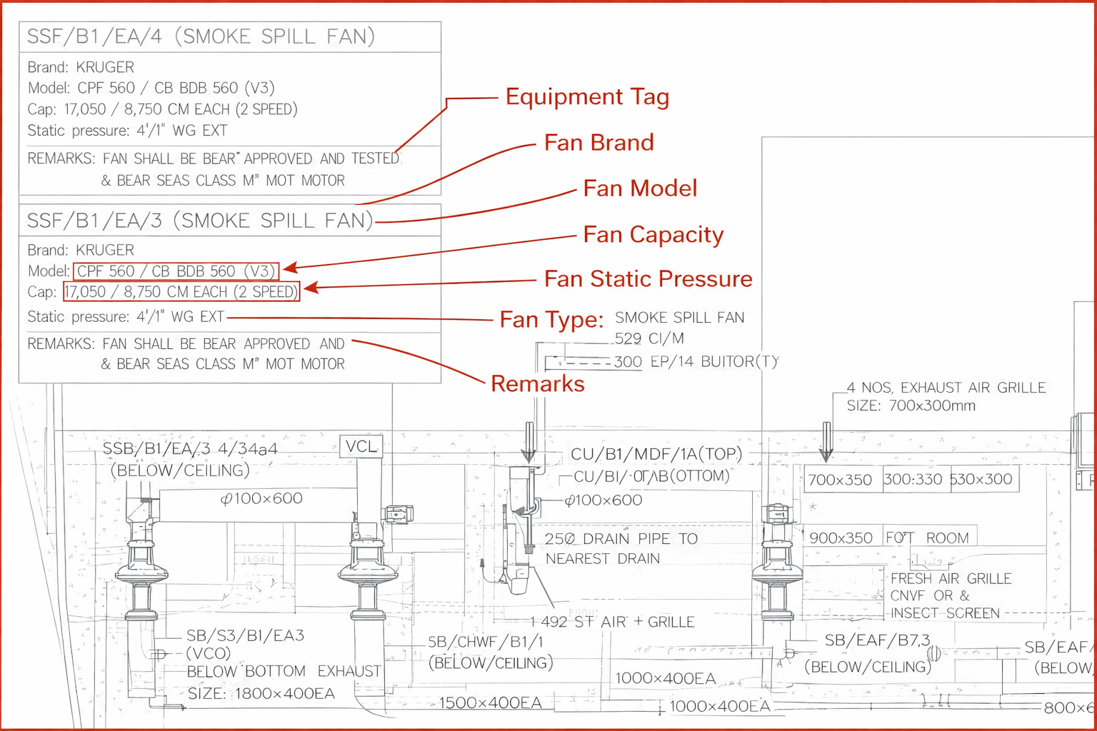
Example Tag:
Meaning:
- SSF → Smoke Spill Fan
- B1 → Basement 1
- EA → Exhaust Air
- 3 → Fan number
Helps identify system instantly
2. Fan Specifications
Includes:
- Airflow (CFM)
- Static Pressure
- Fan Type
- Motor details
Static Pressure Units
| Unit | Meaning |
|---|---|
| in.WG | Inch Water Gauge |
| Pa | Pascal |
| psi | Pressure |
3. Dual Airflow Systems (Important)
Example:
- Normal mode: 8750 CFM
- Fire mode: 17500 CFM
Used in smoke extraction systems
4. Duct Size & Reduction
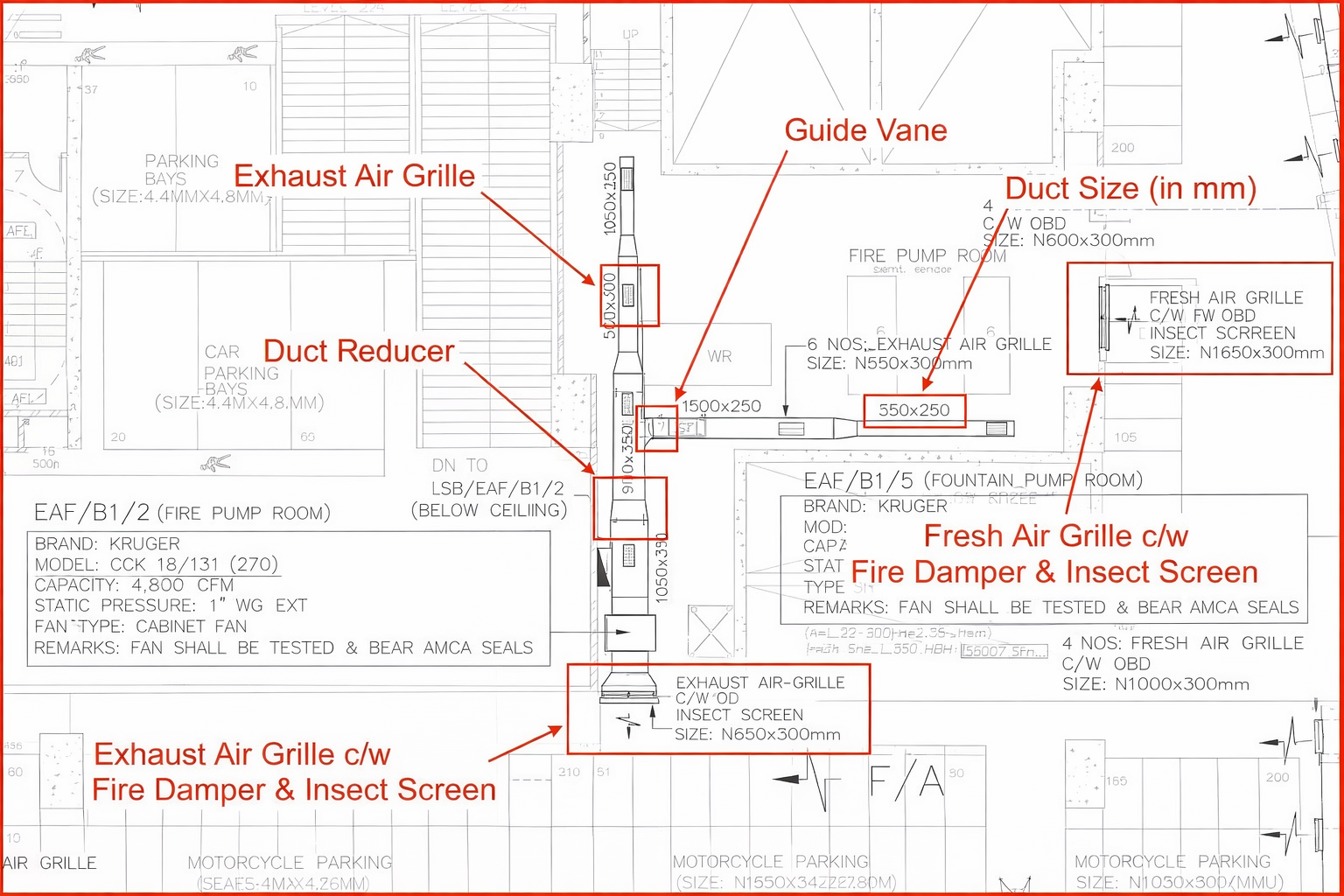
Example:
Width × Height
Key Concept:
- Duct size reduces after each grille
- Saves cost and improves efficiency
5. Common Duct Fittings
- Elbows (90°, 45°)
- Reducers
- Tees
Guide vanes used in bends for smooth airflow
6. Grilles & Dampers (Ventilation)
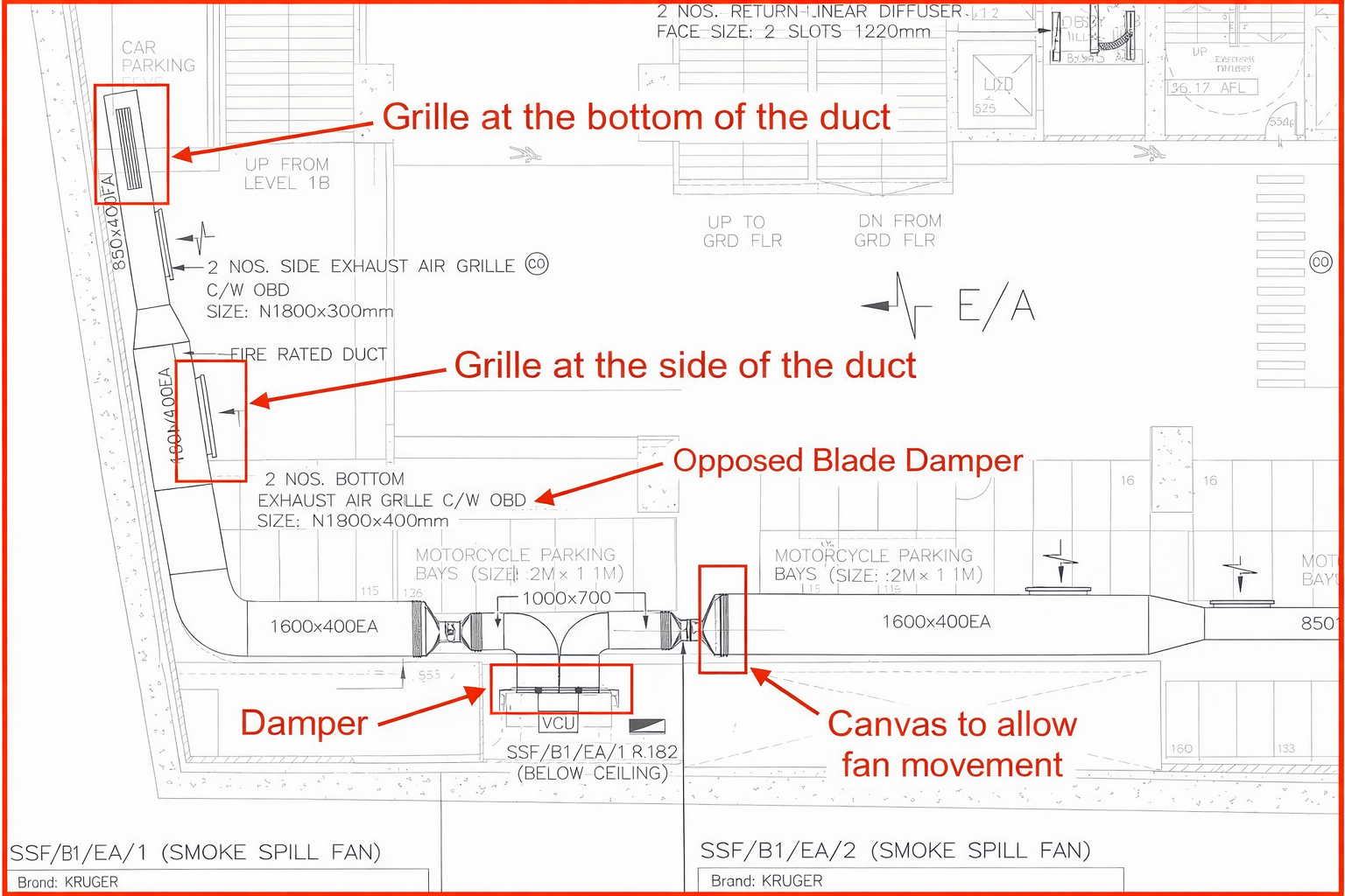
Common Acronyms
| Acronym | Meaning |
|---|---|
| EAG | Exhaust Air Grille |
| FAG | Fresh Air Grille |
| FD | Fire Damper |
| NRD | Non Return Damper |
7. Canvas Connection
- Flexible connection before/after fan
- Prevents vibration transfer
8. Airflow Direction & Units
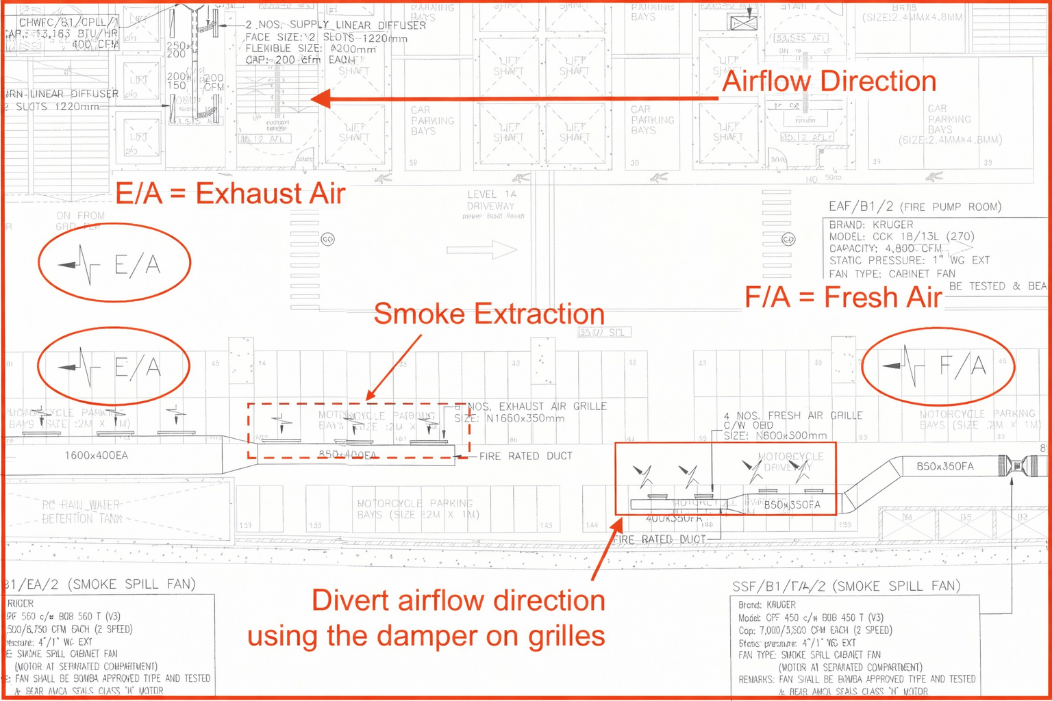
Common Terms:
- EA → Exhaust Air
- FA → Fresh Air
- OA → Outdoor Air
Units:
- CFM
- CMH
- L/s
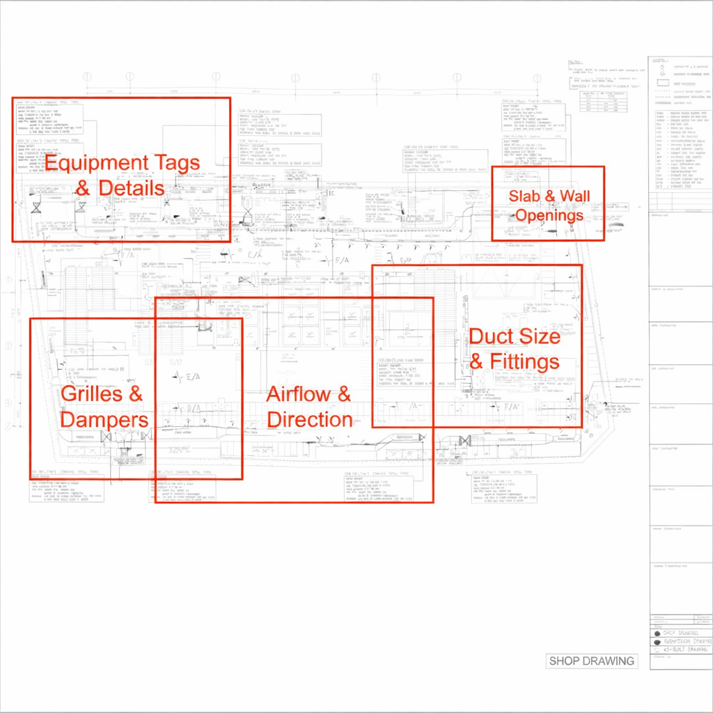
9. Slab & Wall Openings (CRITICAL)
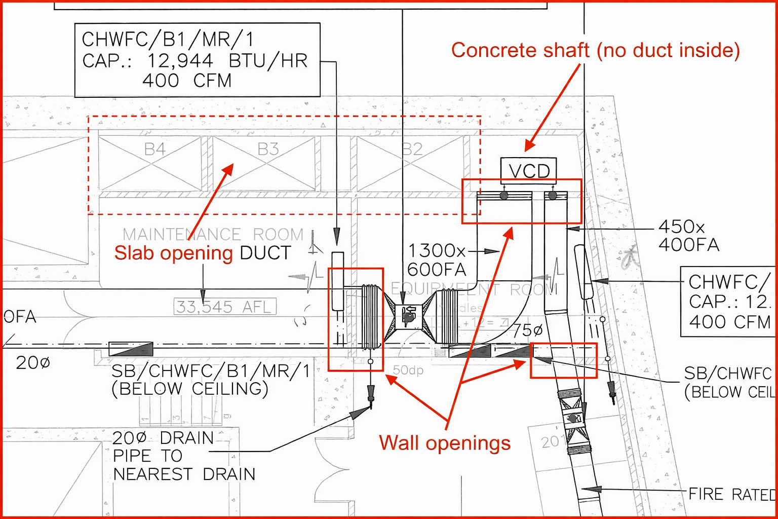
Whenever duct passes through:
- Wall → Sleeve + Fire damper
- Slab → Opening required
Missing openings = major site issue
Important Field Insight
Many engineers fail due to:
- Missing openings
- Wrong duct routing
- Coordination issues
Step-by-Step Practical Method
1. Start with Equipment
2. Trace duct path
3. Read airflow
4. Check sizes
5. Identify terminals
Common Mistakes to Avoid
- Ignoring legend
- Not checking airflow
- Missing openings
- Wrong duct size interpretation
Need Help Understanding HVAC Duct Drawings for Your Project?
Get Expert Guidance from Vipul HVAC Solution Pvt Ltd
Reading HVAC drawings is critical—but executing them correctly is what ensures project success. Avoid costly mistakes, installation errors, and airflow issues with professional HVAC support.
What We Offer:
- HVAC Duct Drawing Review & Validation
- Complete HVAC Design & Drafting Support
- Airflow Calculation & Duct Sizing
- Shop Drawing Preparation & BOQ
- On-Site & Remote HVAC Consultation
Perfect For:
- HVAC Contractors & Installers
- Builders & Developers
- Consultants & Engineers
- Industrial & Commercial Projects
📞 Talk to HVAC Experts Today
📱 Call / WhatsApp: +91-9825636606
🌐 Website: www.vipulhvacsolution.in
📧 Email: info@vipulhvacsolution.in
Free Expert Consultation Available
Get a FREE initial review of your HVAC duct drawings and ensure your project is designed for performance, efficiency, and long-term reliability.
Conclusion
Reading HVAC duct drawings is a fundamental skill that ensures successful installation, proper airflow distribution, and system efficiency. By understanding equipment tags, duct routing, airflow direction, and symbols, you can confidently execute any HVAC project.
Frequently Asked Questions (HVAC Duct Drawings)
Q1: What is an HVAC duct drawing?
An HVAC duct drawing is a technical layout that shows duct routing, equipment location, airflow direction, duct sizes, and air distribution components like diffusers and grilles.
Q2: How do you read HVAC duct drawings step by step?
Start by identifying equipment such as AHU or FCU, then follow duct routing, check duct sizes, identify diffusers and grilles, and finally verify airflow direction and values.
Q3: What do duct sizes mean in HVAC drawings?
Duct size represents width and height for rectangular ducts (for example 600 × 300 mm) and diameter for round ducts. These sizes do not include insulation thickness.
Q4: What is the meaning of CFM in duct drawings?
CFM stands for cubic feet per minute and represents the airflow volume passing through ducts or supplied to a space.
Q5: What are common symbols used in HVAC duct drawings?
Common symbols include arrows for airflow direction, rectangles for ducts, circles for round ducts, and abbreviations like VCD for volume control damper and FD for fire damper.
Q6: What is the difference between supply and return air ducts?
Supply air ducts deliver conditioned air into the room, while return air ducts carry air back to the air handling unit for recirculation.
Q7: What is a VAV box in HVAC drawings?
A VAV or variable air volume box is a device that controls the amount of airflow supplied to a specific zone based on temperature requirements.
Q8: Why are duct drawings important in HVAC projects?
Duct drawings are important because they guide installation, ensure proper airflow distribution, reduce errors, and help in coordination with other services.
Q9: What are common mistakes when reading HVAC duct drawings?
Common mistakes include ignoring the legend, misinterpreting duct sizes, overlooking airflow direction, and missing slab or wall openings.
Q10: How do I identify airflow direction in duct drawings?
Airflow direction is indicated by arrows drawn on ducts. These arrows show how air moves from equipment to diffusers or exhaust points.